Technology
A hand-made computer from the PIC24
1. Introduction
1.1 This project represents a handmade computer with a PIC24fj256gb110 at the centre. Firmware is provided as text files, as source files and header files.
1.2 The ‘computer’ was made with the idea of seeing what I could do with a PIC24. The only part number I had around is the Plug in Module variant for the Explorer 16 board.
1.3 ICSP loading of the files was done with an ICD4 plugged into the Explorer 16. Code was developed on the MPLAB X IDE. Language is C, compiled by the xc16 compiler, v1.26.
1.4 Again, the ‘computer’ was motivated by some dream of making a standalone device which could process commands from a keyboard, and respond on screen, drawing on an SD Card for storage and to some extent as a temporary pseudo RAM for holding text to be processed.
1.5 Admittedly, I didn’t know much about the workings of a computer at the time I began, about three months ago, early January, 2020. And since then, from what I have learned from this little device, I’ve moved on to working with web-based system to do the same thing.
1.6 Complexities of C Coding did not put me off, so much as the incredible slowness of the method of using the SD Card as a database for large amounts of data. And, added to the complexity of implementing a large semi-intelligence (the WordNet 3.0 software), I realised that to continue was folly.
1.7 User Interface as it stands recognises a bare handful of commands, which must be input without deleting any letter (rushing onward, I thought to do this later).
1.8 On boot up, a cursor is at the top left of the screen.
1.9 Photographs

2. Commands
Commands can be seen in the main.c file, as: ‘files’ – to view all files on the SD Card ‘open’ – to open and view any file contents on the card ‘write’ – to create a file ‘Dictionary’ – to enter dictionary mode, and to view the output of WordNet for any particular word. (To see more about the WordNet project, developed at Princeton University, see https://wordnet.princeton.edu/).
3. Fatfs
The main.c program file can be customised. Commands can be created. Those which exist at the moment are derived from the Fatfs program developed by Elm Chan, which, using the SPI protocol, communicates with the SD Card; it leaves us only with the effort of writing the C commands into a format which allows keyboard and screen use. The most up to date SD card formats are supported. I found that most of the functions which Fatfs offers had to be switched on in order to use the functions which I wanted to use.
4. Text documents
All files loaded onto the SD Card from your PC can only be read by the PIC if they are saved as UTF-8 files in order to avoid difficulties with line end codes and the like.
5. The screen
The screen is a small TV screen of the kind which we used to have playing DVDs and plugged into an arial for TV reception. It has a composite video socket, and this is what the PIC feeds into. Using the SPI and an Output Compare pin, I was able to follow Lucio di Jasio’s scheme outlined in the ‘Programming 16-bit PIC Microcontrollers in C’ series. I had to fiddle about with the parameters which he used due to some interference with the other things going on in the PIC itself. Scrolling is enabled with use of a simple state machine which handles the number of rows and allows only 20 rows to appear at any one time. It’s a bit glitchy, but it does allow scrolling of text.
6. The Keyboard
The keyboard is a straightforward implementation of the Microchip Libraries for Applications firmware library for the USB Host. The application delivers a single keystroke at a time, which I then process into a global variable and manipulate inside main.c with a circular buffer. See the app_host_hid_keyboard.c file.
7. UART for input / ouput
There is no UART functionality, and printf and associated input and output library functions are not used in the firmware. I had to develop custom functions, namely putsV() for printing to screen, and getKeyCode () for input and output. Besides which, I noticed that the printf library function has to be manually installed on the PIC and takes up a large amount of program memory.
8. A C Interpreter
I attempted at one point to bring in a C interpreter by Herbert Schild into effect on the PIC24fj, but the data memory was not sufficient. Limited by time, and by any reason to continue with this ‘folly’, or hobby horse, I didn’t pursue it further. Obviously, I was in part motivated by a desire to do something with the PIC24f which had been done with the PIC32 by Geoff Graham with his Maximite.
9. Practical Applications
Objectively, this design allows me to load firmware up which can test out C Code. While there are C emulators or compilers online to test out C programs designed for user interaction (basic AI programs), I prefer my PIC for the moment. Doing this kind of thing means using strings, pointers, structures, arrays and dimensional arrays, and the like, and with the stack and the heap – usually remote and unused with the PIC. It gives me some exercise in this area of the C language.
10. Future
In order to be able to get this thing off my desk, and work on something else, and so as to be able to free up the Explorer 16, I will attempt to put the firmware into the PIC24f128gb002 in the near future. This 28 pin part number comes in a DIP package, which is obviously much preferred for small projects like this where getting a PCB made is not something I’m considering.
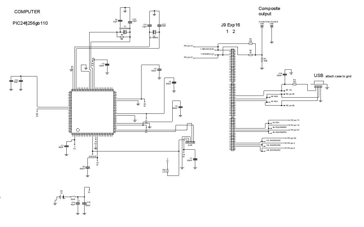
11. Schematic
Here is the schematic. Note the pinout from the PIC24f:
12. A note on the firmware / code
This is a rushed and scruffy code, with a few arrays declared are not used. All the user interaction has been stuffed into the main.c file. State machines are not usually used where they should be, which has led to overuse of ‘flags’.
13. Pin allocation notes:
Pin allocations, using Peripheral Pin Select, are in pin_manager.c. SD Card pins are initialised in pin_manager.h, including CS on RE3. USB pins are not declared because they are standard and cannot be changed. The SD Card is using SPI2; Video is using OC3, OC4 (no pin) nd SPI1.
14. Configuration bits
for the firmware are in: system_usb.c file.
15. Timers and interrupts:
T2 is used in text.c module, for video. PR2 is set so as to generate lines on screen.
Timer3 is used by the USB module.
OC3 and OC4 have interrupts enabled
16. RTOS
A real time operating system was not used. Rather, the USB, screen, and the SD Card were co-ordinated in such a way during set up that they do not interfere with each other. Initialisations of each are repeated throughout the main.c module in order to avoid conflicts.
17. Downloads
17.1 Firmware (zip)
17.2 Schematic
17.3 Photographs

18. Copyright, Jason Powell, March 2020
Design Jason Powell, 2020.