Technology
Complex I2C communication - MM7150 Motion module with LCD display for Inclinometer
1. Introduction
1.1 The project below is a demonstration only.
1.2 Assuming that my pins are set up correctly for the PIC16 and the PIC24 (see projects two immediately prior to this one), and that the I2C is set up correctly for reception, and for transmission on both sides, then I am left with a single problem: the speed of the transmission by the I2C2 module.
Note, the I2C2 between PIC24 and PIC16 must be right in itself because I am using the mcc code generated for the chip. This same mcc code library set of functions is also used for communicating with the MM7150, so let us assume it works.
(The mcc code is notoriously difficult to read at first, and you may find out here how to use it for basic things.)
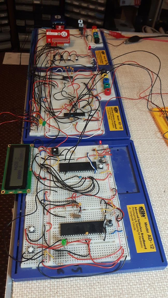
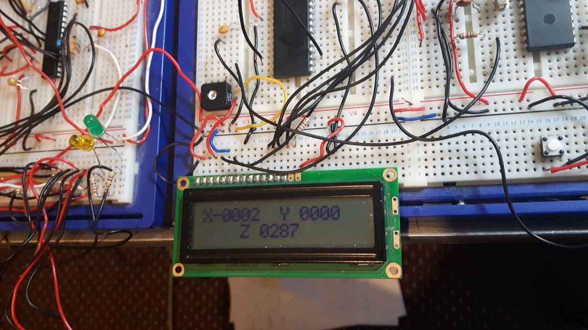
Here is what my breadboard looks like. For your consideration.
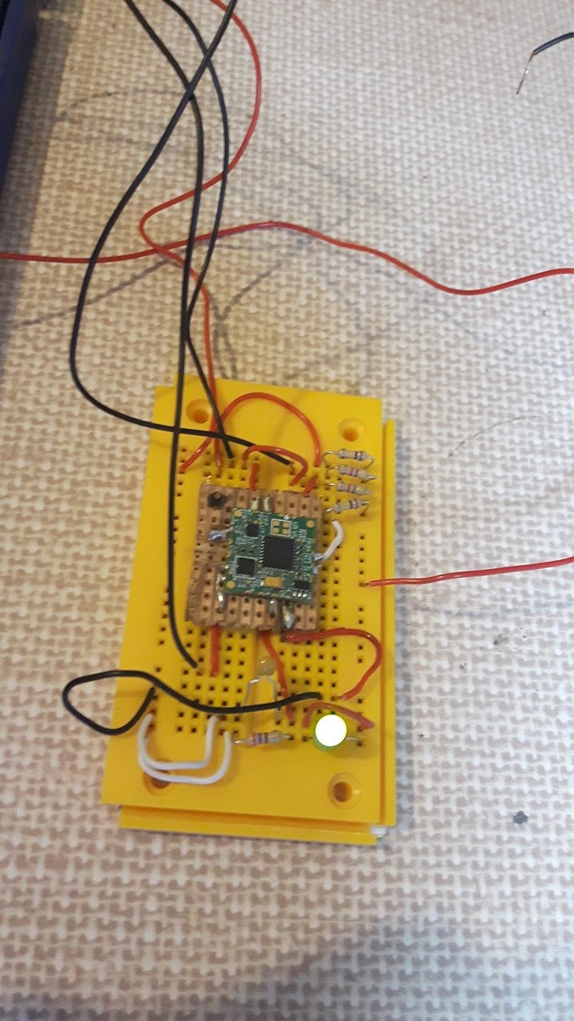
And here is the motion module:
2. Set up
Assuming the code itself is correct, then I was puzzled that there was no actual communication from one to the other chip, PIC24 master to PIC16 slave. The fault lay with the clocks.
Examination of the clock speeds:
Slave clock setting is default. That is,
In configuration bits, FOSC = INTOSC.
I have not assigned any value to OSCCON. So, it resorts to default settings.
Datasheet, page 73 says that the default settings for the PIC16F1939 is 500KHz.
That is, the default value for OSCCON is not 0x00, but 0x38 (0b00111000).
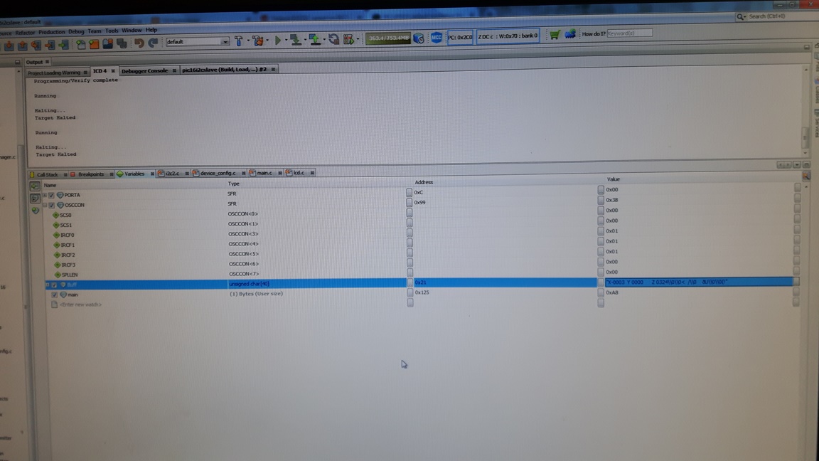
I verified that the OSCCON is indeed at this setting by using the MPLAB debug tool and watch window for the these SFRs.
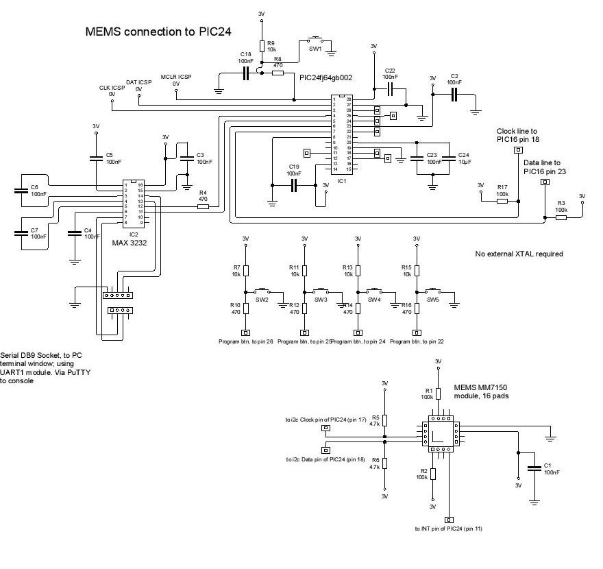
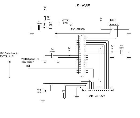
Master and Slave schematics:
On the master side, with the PIC24FJ64GB002, the clock is set up as follows:
Configuration bits:
POSCMOD = OFF
So I have the 8MHz Fast internal RC oscillator with post scaler.
Although my config bits show that the PLL is enabled, this does not come on because there is no external oscillator. So, looking at the OSCON and CLKDIV in the debug window, I have:
OSCCON = 0x7740, which means: Fast RC oscillator with postscaler
CLKDIV = 0x3100, which means: clock divided by 2 (for 4MHz clock)
Given a 4MHz clock, then the ideal I2C baud rate values loaded into the I2C special function register I2CBRG should be as follows:
For the MM7150, which can accept a clock of 400KHz, BRG = 9 (0x0009)
For the PIC16F, which can accept a clock of 100KHz, BRG = 78 (0x004E)
See PIC24FJ64GB002 datasheet, page 183.
These are the values loaded into the respective I2CBRG registers.
This is important because, until the 100KHz reception speed was taken into account, I could not get the PIC16 to respond, even though it was clear that there was a transmission by I2C.
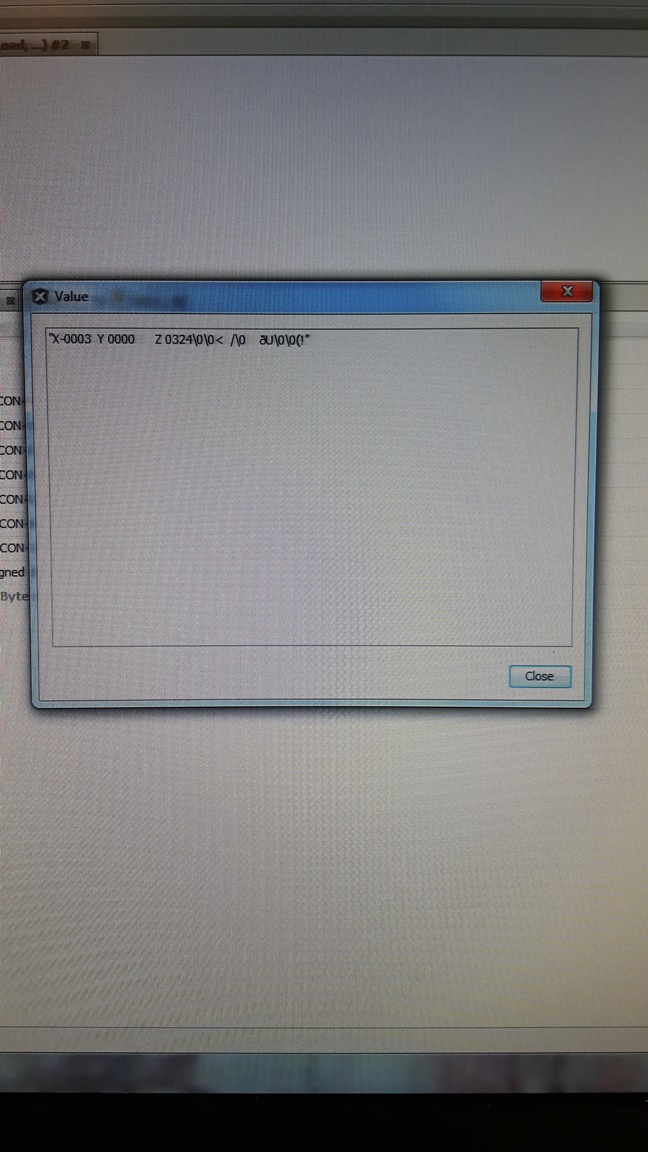
See here for the values of the watch windows for the OSCCON settings for the PIC16; and the transmission of the TX buffer to the slave, aligning with the LCD read out, further on.
3. Notes on Firmware
Because the LCD is a slow device with its own timing restrictions, I have had to slow the refresh rate for any transmission for the LCD. That is, the I2C clock is what it is, but any transmission must be followed by a delay so that the PIC16F and the LCD can handle the current transmission.
So, inside the PIC24F system.c I put the MasterWrite function, and a delay to allow the LCD to process this command before accepting a new transmission.
This delays the accuracy of the MEMS device as a whole. I also make use of the string concatenation performed by the original microchip code. A string of up to 40 bytes is sent at any time, and is preformatted to look nice on the LCD screen of the slave.
Note also that the LCD screen has been formatted to receive strings of up to 40 characters, and goes to a new line after 16 of them. The string is sent from the master so that the 17th character will go to a new line, and there are blank spaces in any string to accommodate this.
Notice also cigarette ash picked out by the camera in the close up pictures.
4. Schematics
PIC16F1939 schematic with lcd
5. Firmware
Download Firmware for Slave PIC16F1939
Download Firmware for Master PIC24FJ64GB002
6. Datasheets
PIC24FJ64GB002 Datasheet
PIC16(L)F1938/9 datasheet - DS40001574C
7. End
Design Jason Powell, 2020.