Technology
8 Microelectronic Motion Sensing on the PIC24f with I2C communications
1. Introduction
1.1 The project below is a demonstration only.
1.2 This is a short project to demonstrate I2C communication between the PIC24FJ64GB002 and the Microchip MM7150.
1.3 Firmware is entirely derived from the demonstration code provided by Microchip, excepting the modification of the code to run it on the 28 pin serial number.
1.4 The MM7150 for prototyping
2. Set up
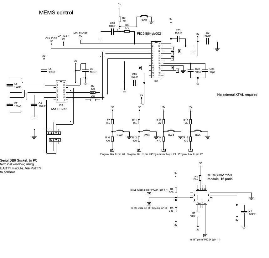
2.1 Schematic and firmware are to be found below.
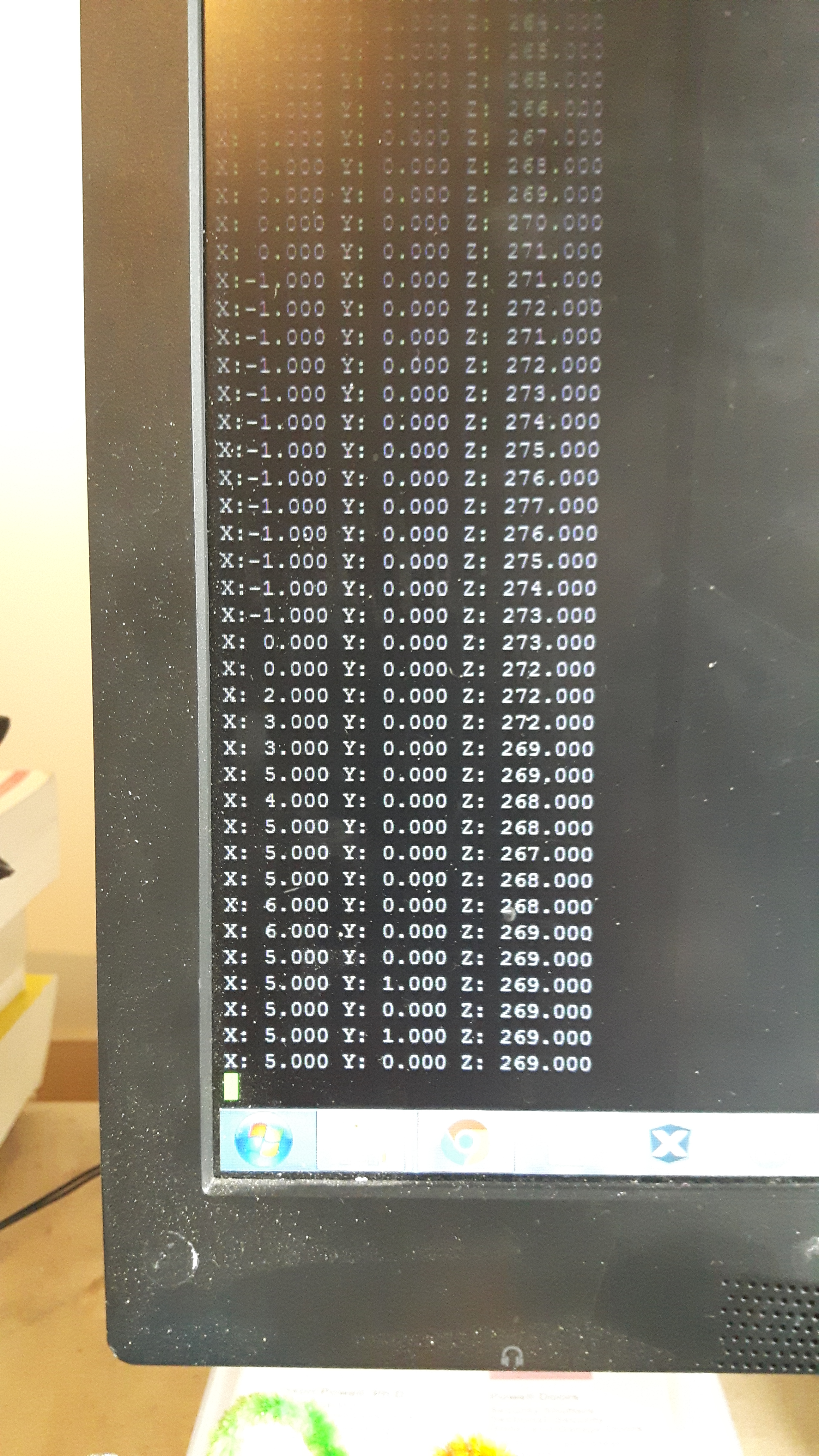
2.2 Data from the MEMS module is sent to the UART and then the Serial port and Console.
2.3 ICSP pins are included in the schematic, which leaves only a couple of pins spare for anything else. Notes, at the bottom, examine in a simple way how to use the PIC24 100 pin devices where the need to use wireless connection to the MRF89X or the like other additional connections would be necessary.
2.4 Baud rate is 9600.
2.5 There is no need for an external crystal; I have found that the internal oscillatory setting works fine (see configuration bits in the firmware), and the MM7150 has a maximum I2C rate of 400KHz clock.
2.6 To program the chip for any of a variety of uses (accelerometer, gyroscope, compass, inclinometer, etc.), the buttons on the board are required.
2.7 Switches: switch to pin 26 is menu cycle up, switch to pin 21 is menu cycle down; pin 25 is reset the menu / device; pin 24 switch is the select/run button.
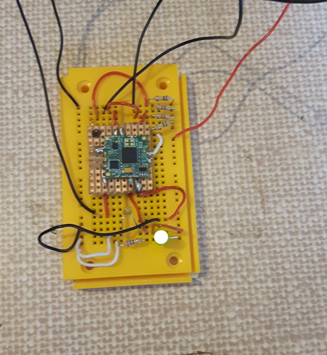
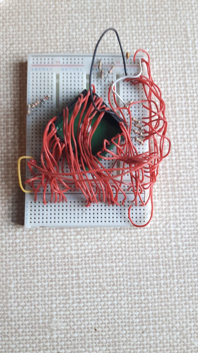
2.8 In order to exploit the extra pins on a 100pin SMD type chip, the following photographs show some of the possible solutions. Some are a bit wierd, showing patience and madness of ambition. But they all work.
2.9 Note that the Peripheral Pin Select set up does not include the I2C module because these pins are not part of the PPS system. I2C1 and UART2 are used here.
2.10 The MM7150 module (based on the SS7150 chip, datasheet below) requires only 5 connections to the host microcontroller; data and clock, and an interrupt pin for use by the MM7150 to alert the microncontroller of incoming data.
The other two pins are optional, and are the reset and wake pins; they are active low, and, not needing them, I have simply attached them to VDD with a 100k resistor.
3. Notes on Firmware
3.1 None
4. Schematics
4.1 The connection of the MM7150 to the PIC24 can be downloaded here.
5. Firmware
6. Datasheets
MM7150 module datasheet
MEMS MM7150 power point presentation
SS7150 chip datasheet
Notes on the shortage of pins on the PIC24FJ64GB002
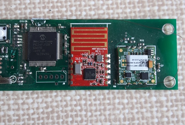
7.1 Ideally, I would incorporate the MRF89X transceiver with the MEMS module, and apply it to some kind of wireless battery powered device. But, due to the shortage of pins, we cannot. Reduced to sending the data from the MEMS to another PIC by way of I2C or something, the board expands. Therefore, using the 100 pin PIC24FJ128 or something, would be advantageous.
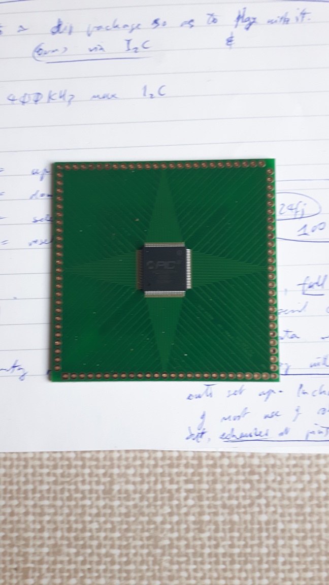
7.2 But how to overcome the problem that you can't prototype the 100 pin SMD versions? See below, for your entertainment.
7.3 Using some enamelled copper
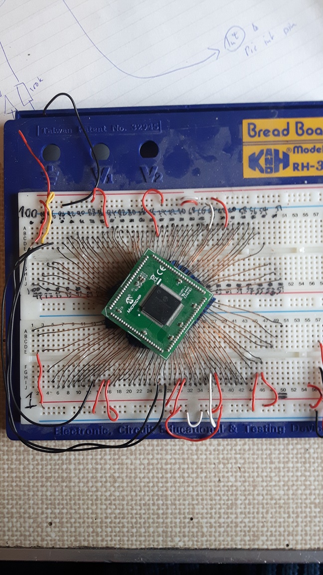
7.4 Using the PIM and rigid copper wire
7.5 Get a pcb made at a PCB factory
7.6 Get a socket adapter
Design Jason Powell, 2020.